![EAGLEで自作ライブラリを作る](https://voltechno.com/blog/wp-content/uploads/2020/01/eagle-logo.png)
電子部品の設計を行っている時、標準ライブラリやPCB Part Libraryにない場合は自らの手でパーツライブラリを作らなければなりません。最近では中国製の電子部品も流通するようになり、そのような部品はモデルが無いケースも珍しくありません。
今回のシリーズではシンボルの作り方からフットパターンの作成、3Dモデルの適用までを解説します。
目次
ライブラリを自分で作ると電子工作の世界が広がる
電子回路の設計をユニバーサル基板からプリント基板に変えると、電子回路設計CADの活用が必須となってきます。CADを使用すれば多層基板や表面実装部品も使用できるようになりますが、その設計作業には電子部品の寸法やモデル図を含んだCADデータを含んだライブラリが必要です
例えば、秋月電子通商の取り扱うパーツ類は非常に安価で少量の購入なら入手性も良いのが特徴ですが、最近は純中国製のパーツも増えています。これらの部品はパーツライブラリの提供が無い事も多く、PCB Part Libraryにデータが存在しなケースも多いので自作ライブラリの作成が必須となります。
「EAGLE」で自作パーツを作る手順
今回はAutodeskのEDA「EAGLE」を使ったパーツライブラリの作成を解説します。
- パーツデータを格納する「パーツライブラリ」を作る
- パーツライブラリ内にパーツ名を登録する
- 回路図に使う「パーツシンボル」を作成する
- パターン設計に使う「フットプリント」を作成する
- パーツ名・シンボル・フットプリントを関連付けして完成
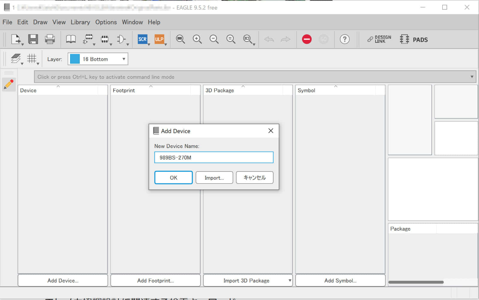
今回は、秋月電子通商で販売されている表面実装用(SMD)インダクター「989BS-270M」を参考にEAGLE用のパーツライブラリを作成してみます。
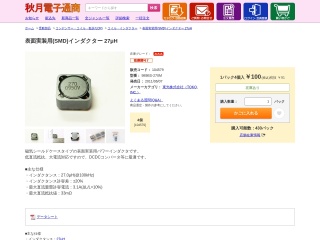
低直流抵抗、大電流対応ですので、DCDCコンバータ等に最適です。
① EAGLEでパーツライブラリを作成
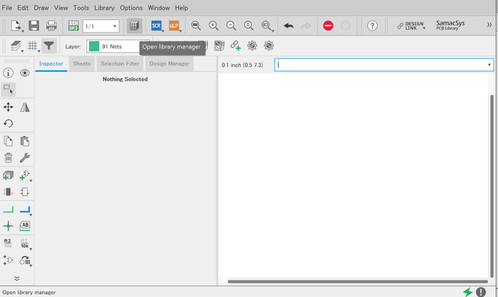
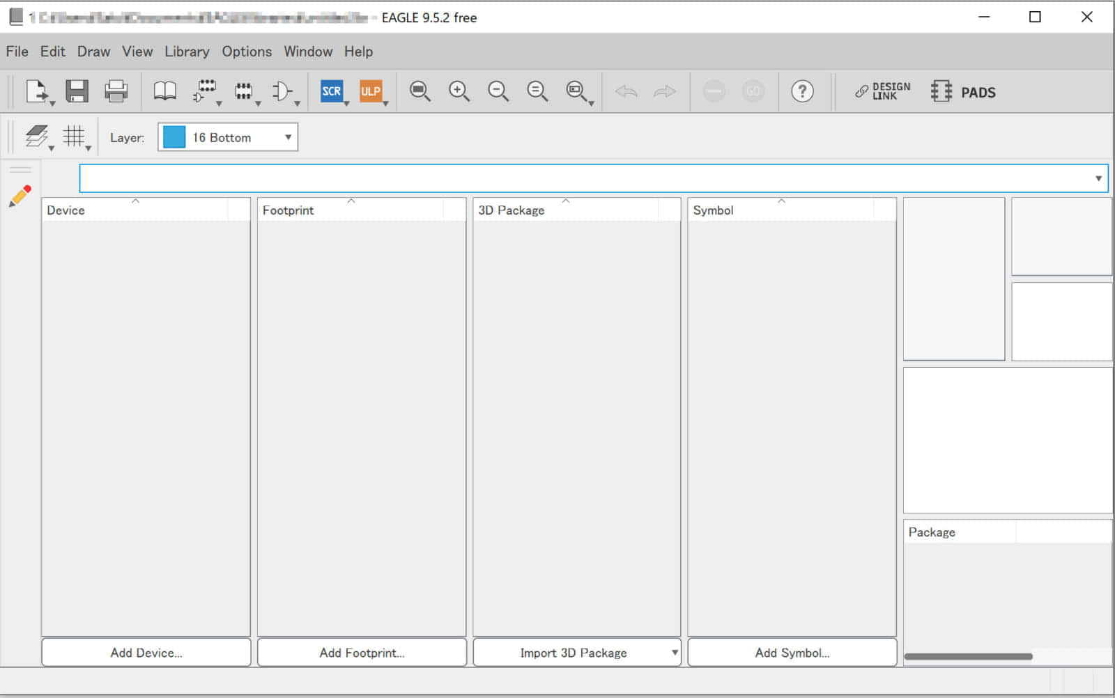
EAGLEでは自作したパーツを全て「ライブラリ」内に格納する必要があります。例えパーツの作成数が1つだけであっても、必ずライブラリを作成する必要があります。
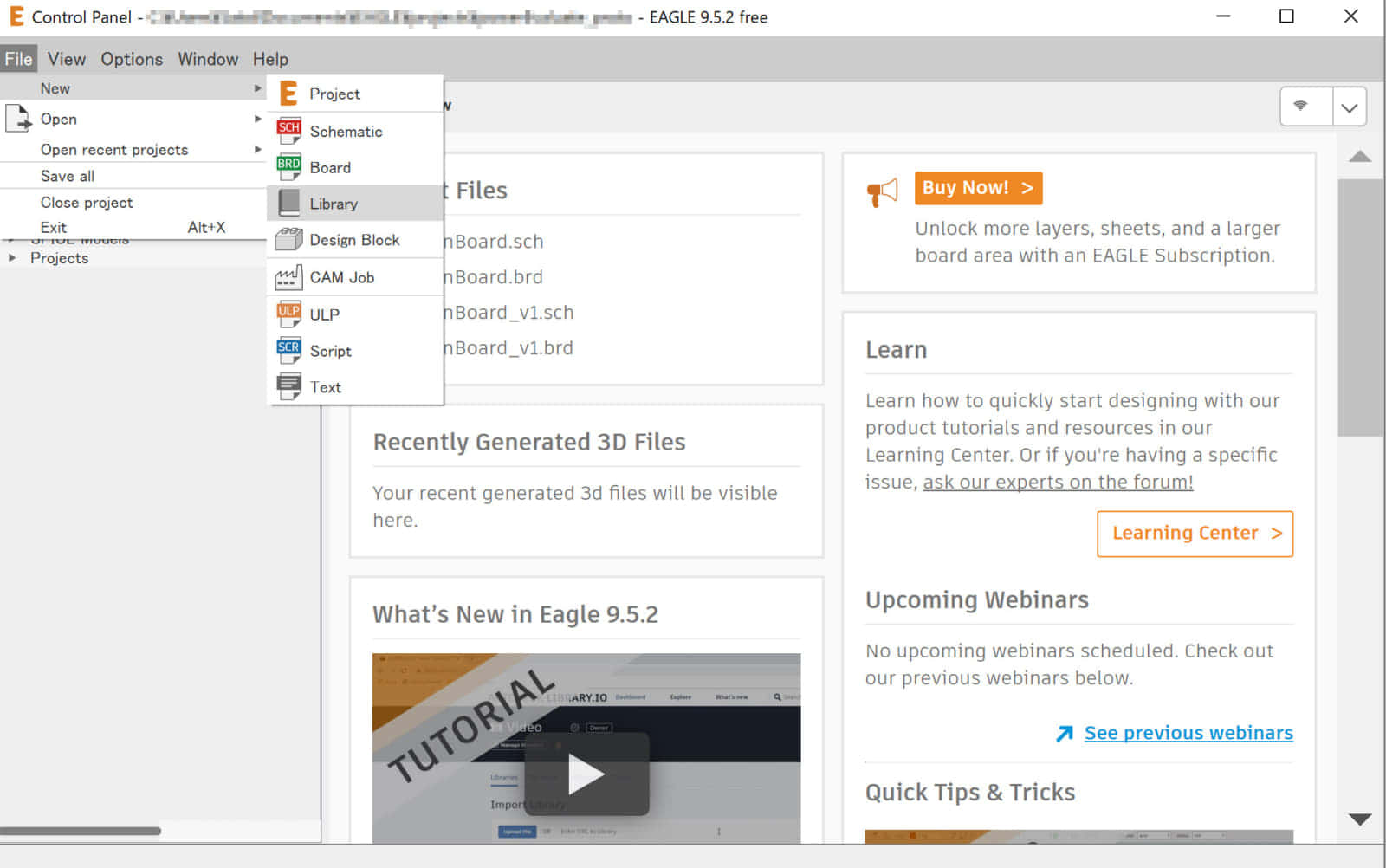
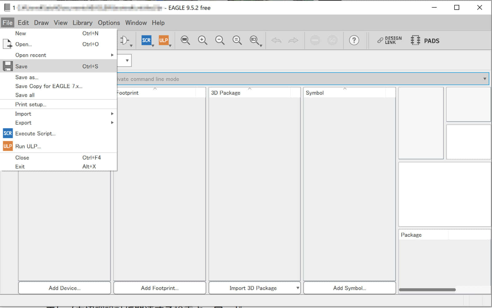
パーツライブラリは「File – New – Library」から新規作成を行います。名前は分かりやすい名称にするのがおすすめです。
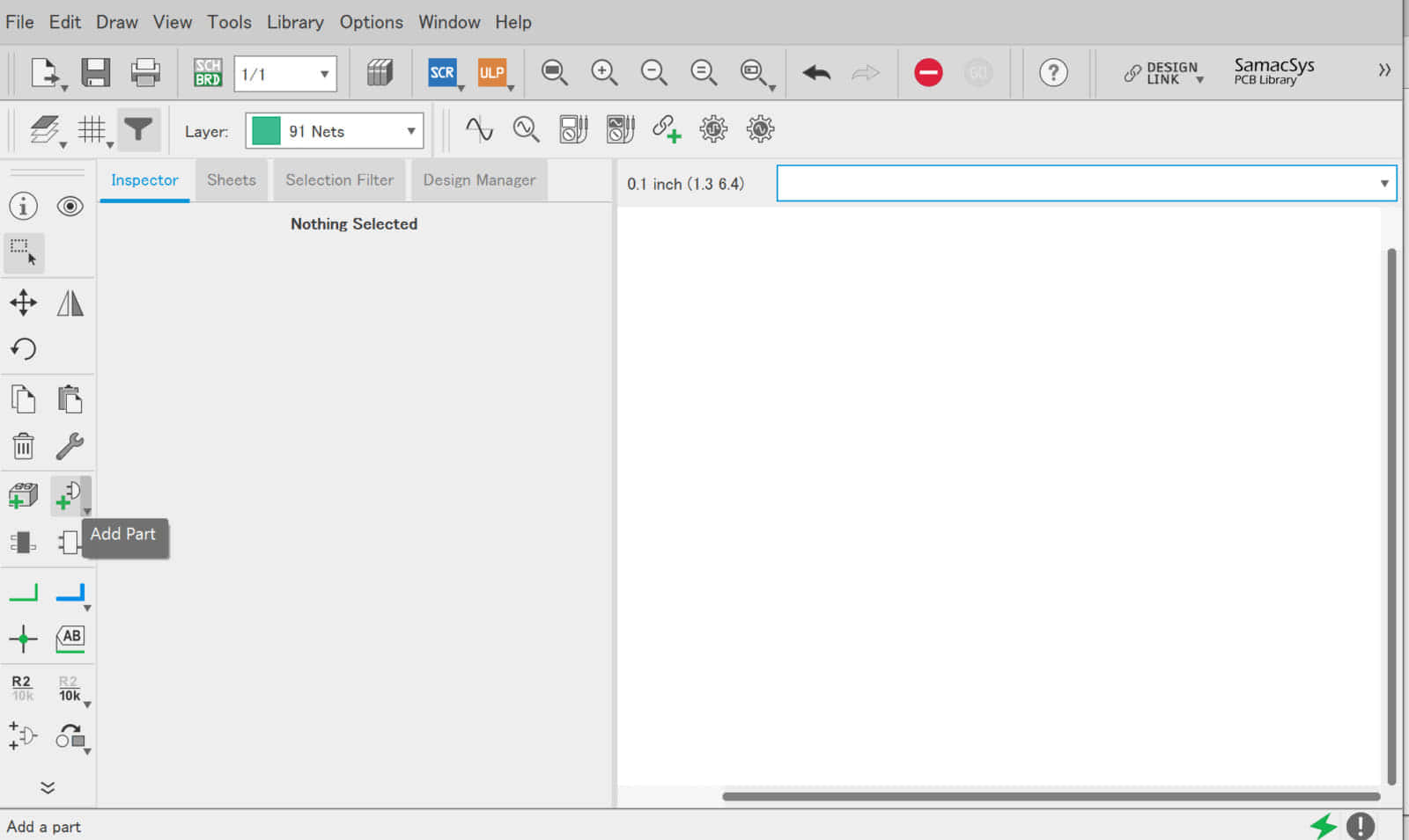
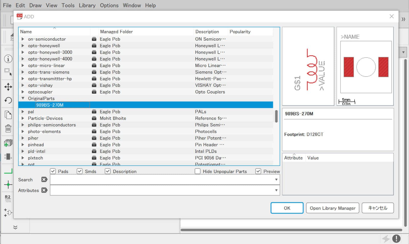
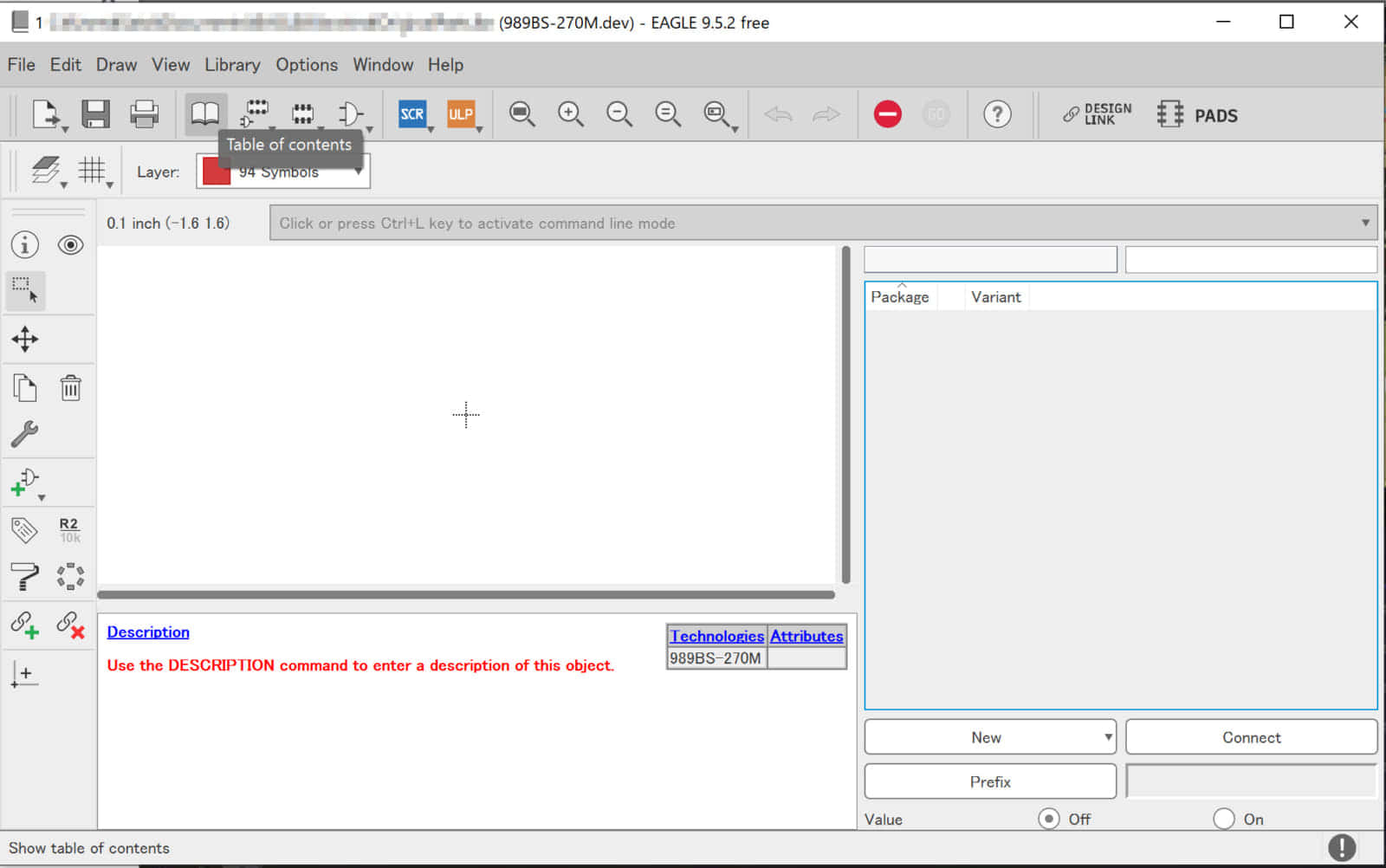
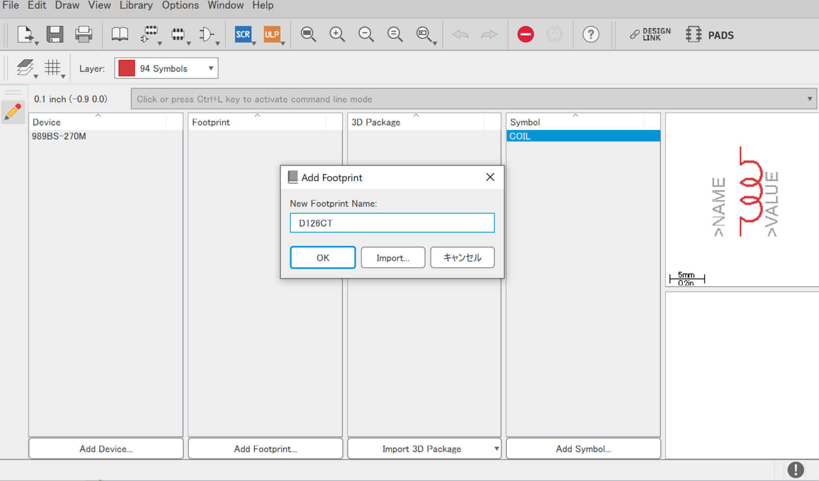
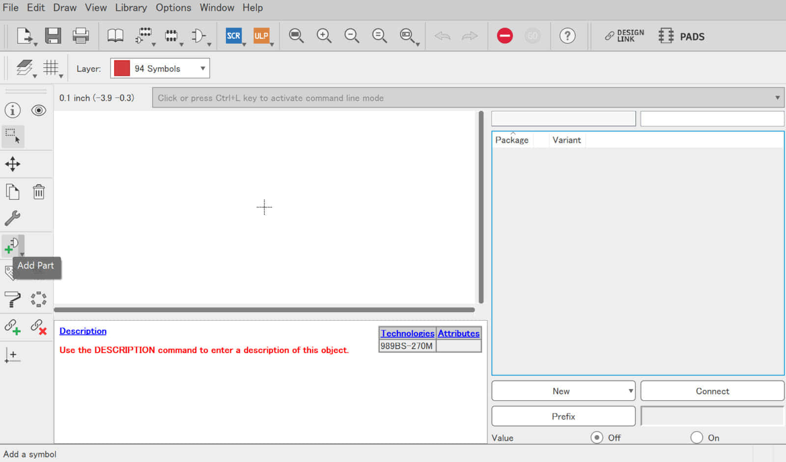
![](https://voltechno.com/blog/wp-content/uploads/2020/01/eagle-library000-768x481.jpg)
![](https://voltechno.com/blog/wp-content/uploads/2020/01/eagle-library001-768x481.jpg)
![](https://voltechno.com/blog/wp-content/uploads/2020/01/eagle-library002-768x481.jpg)
② パーツライブラリ内にパーツ名を登録
パーツライブラリを作成したらパーツの作成に進みます。パーツ名の指定を行うDeviceでは、シンボル・フットプリント・3Dモデルの関連付け、及び配線情報や部品の接頭辞情報などが格納されます。
画面左の「Device」バーの「Add Device…」から登録したいパーツの製品名を登録します。
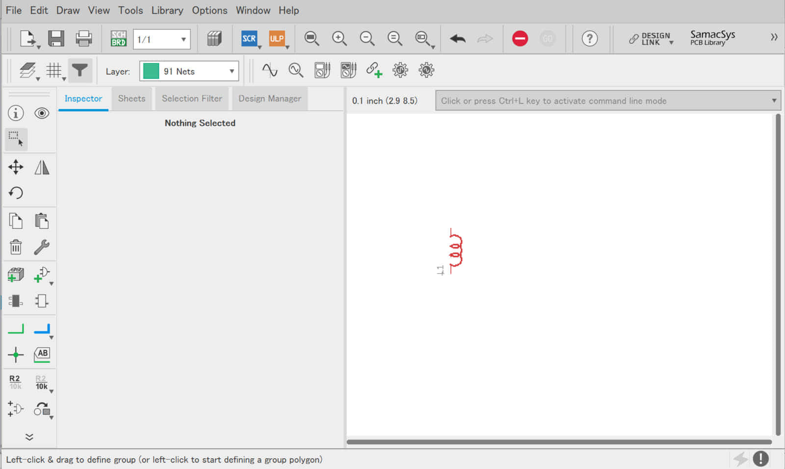
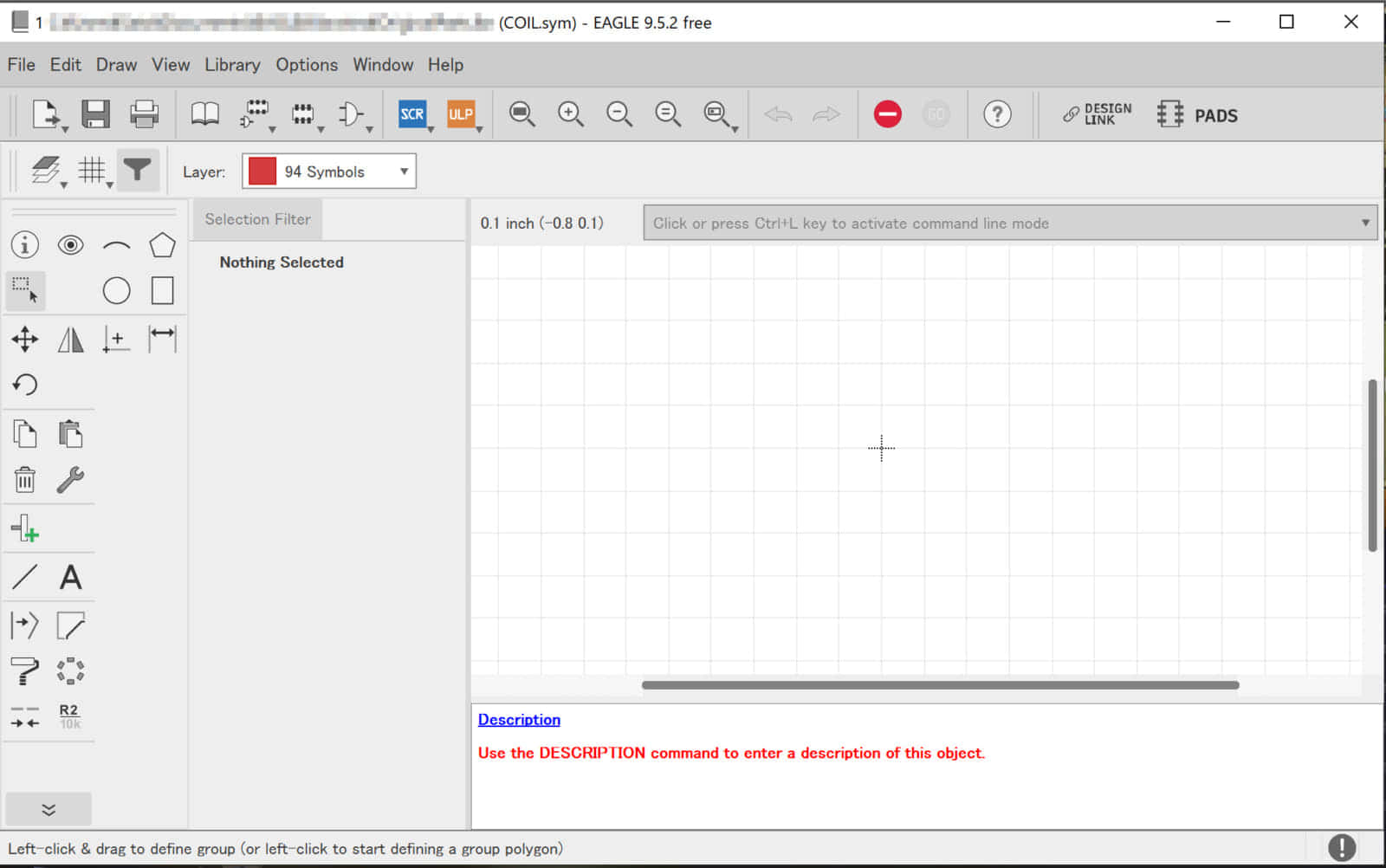
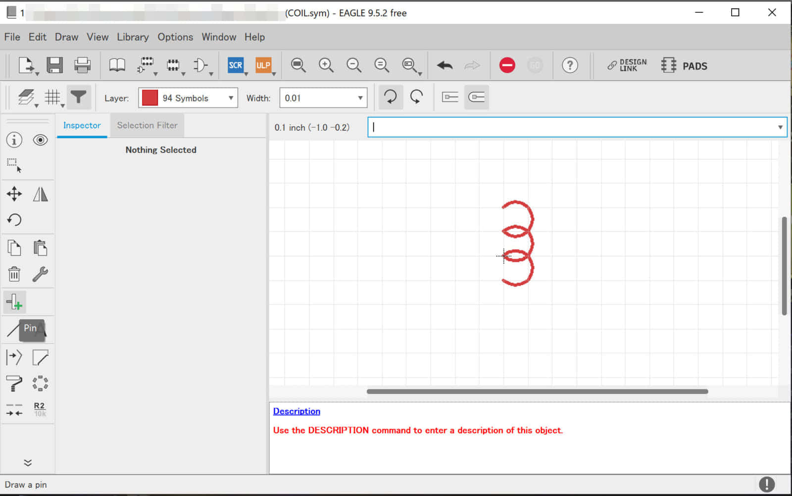
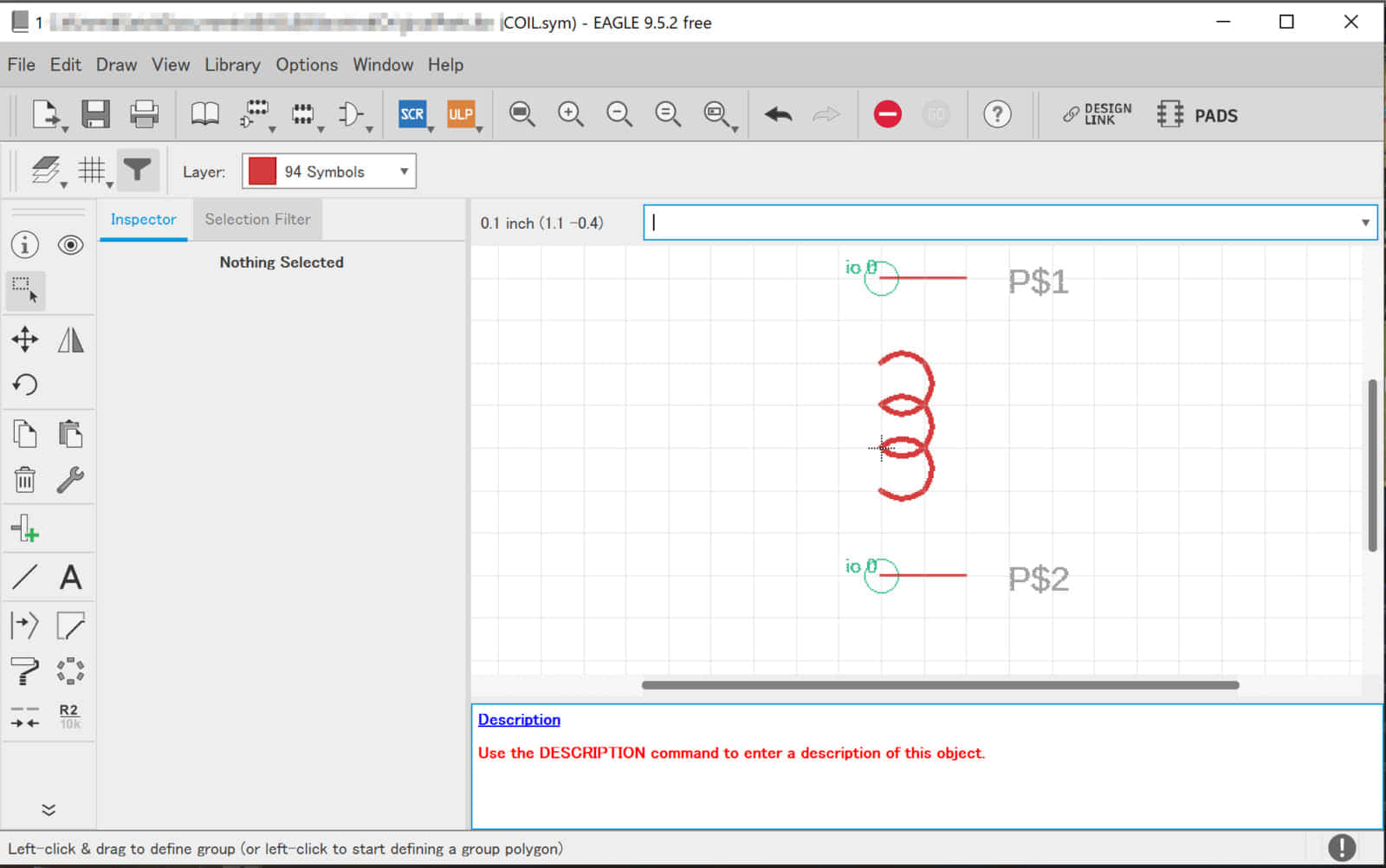
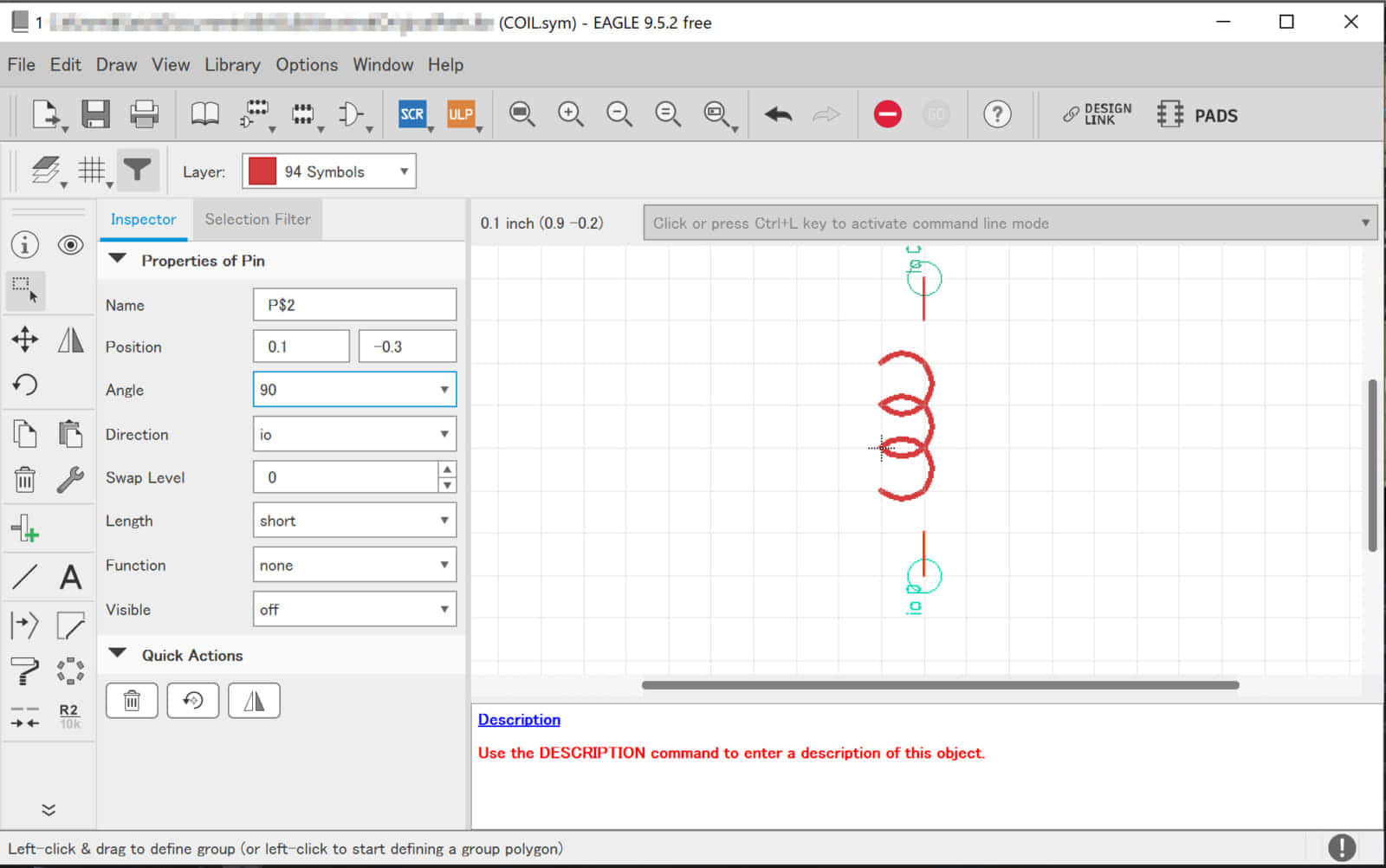
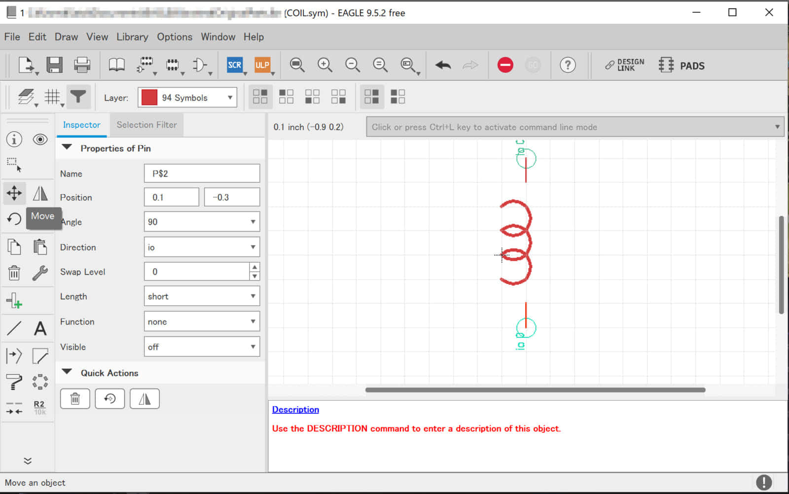
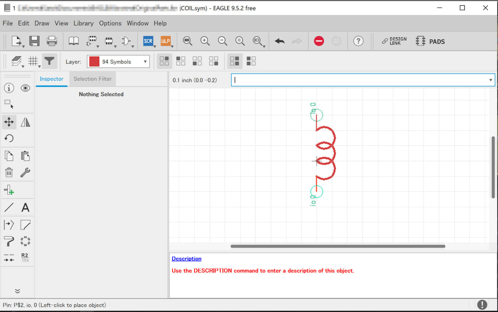
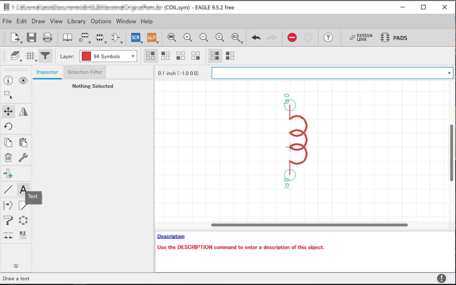
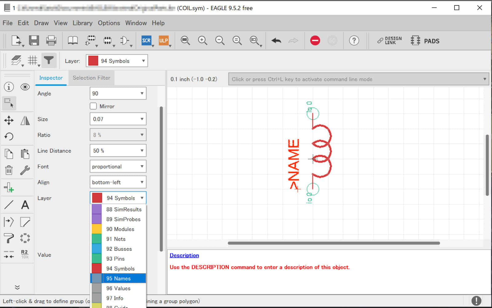
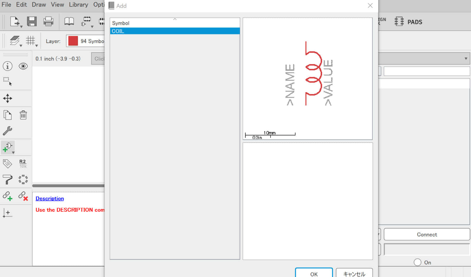
![](https://voltechno.com/blog/wp-content/uploads/2020/01/eagle-library004-768x481.jpg)
![](https://voltechno.com/blog/wp-content/uploads/2020/01/eagle-library005-768x481.jpg)
③ 「パーツシンボル」を作成
パーツシンボルとは、回路図上で表される回路記号です。一般的にはJISなどで策定された汎用的な回路記号を使用しますが、特殊なスイッチや、マイコンを回路図に収める場合などにはシンボルを新しく作らなければならないケースも多いです。
パーツシンボルの作り方は大きく分けて2通りあり「0から作る方法」と「他のライブラリからインポート」する方法があります。
今回は「0から作る方法」で進めますが、実際のシンボル作成で0から作る必要はほとんどありません。一般的には、ほかのパーツシンボルをインポートして形状を調整する方法が取られます。
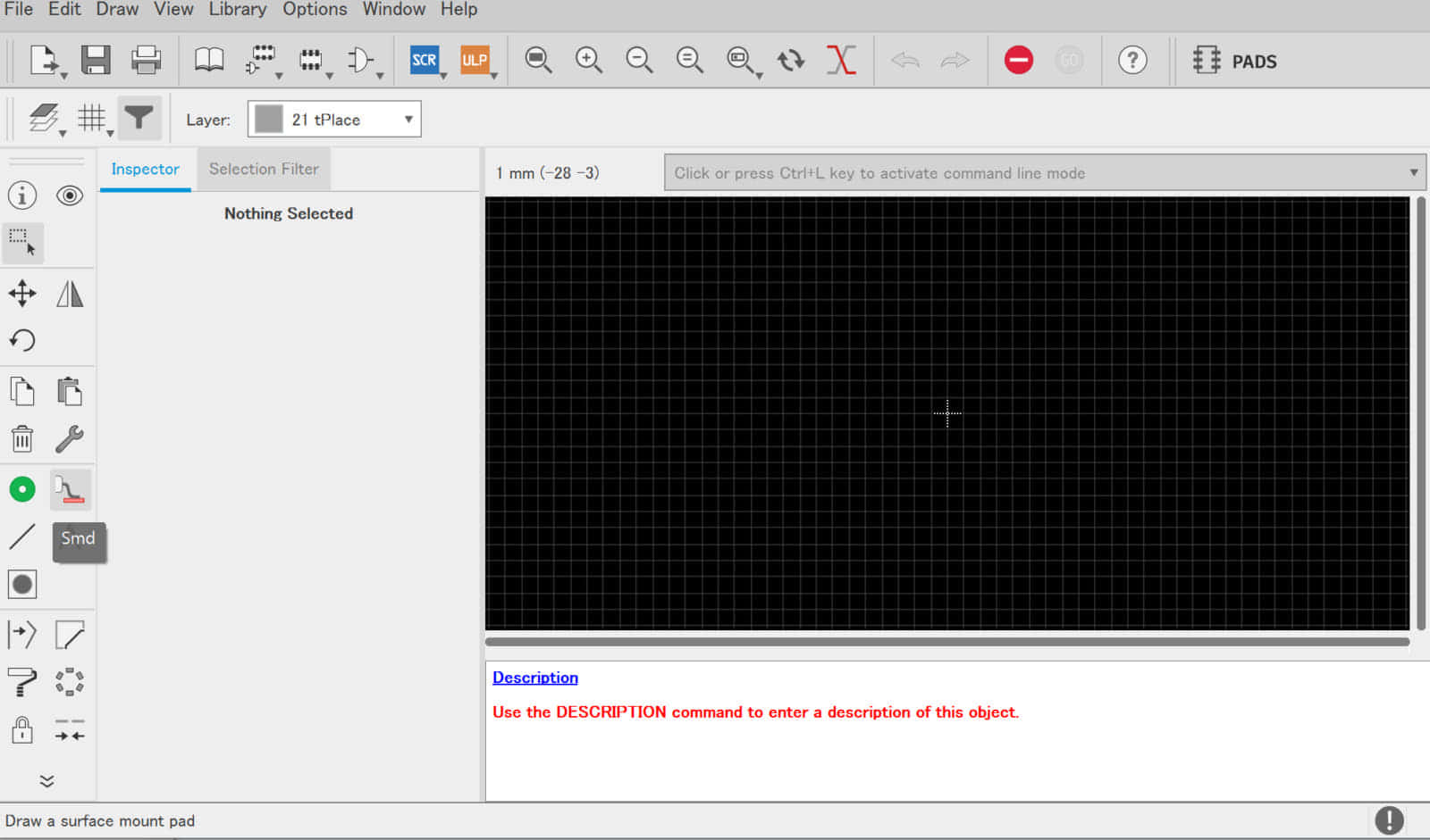
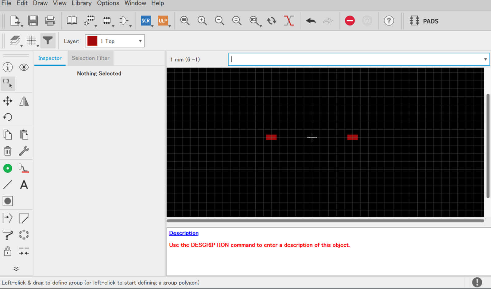
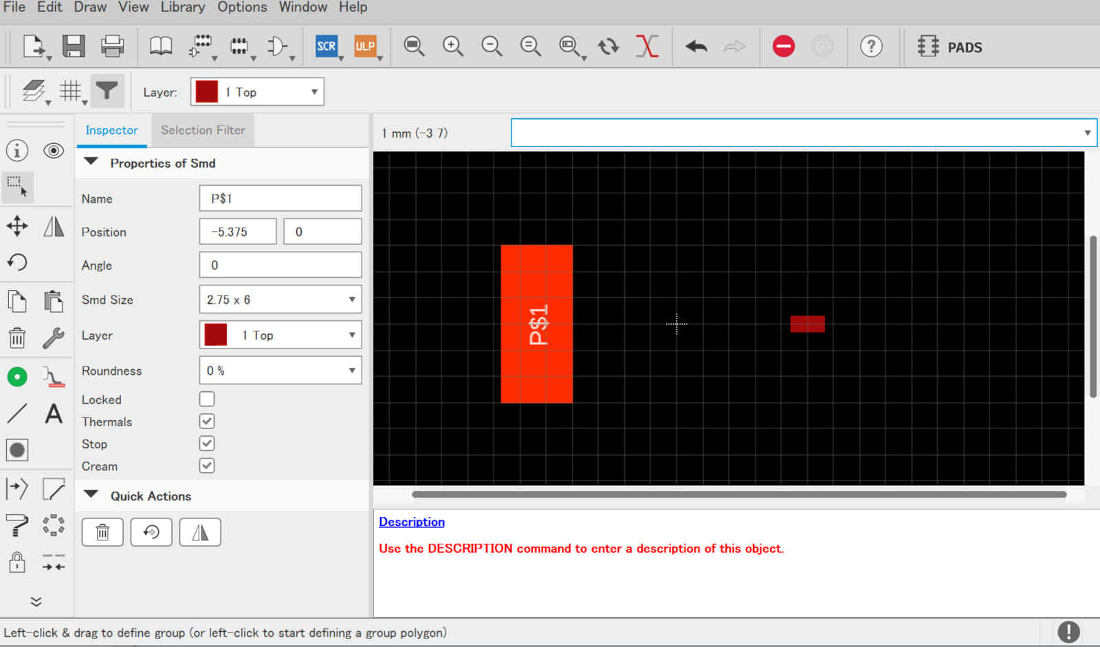
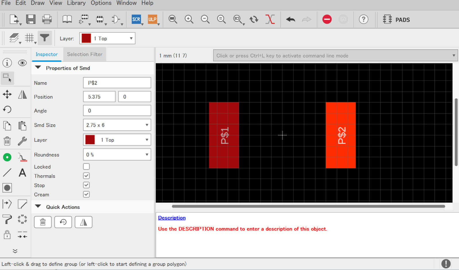
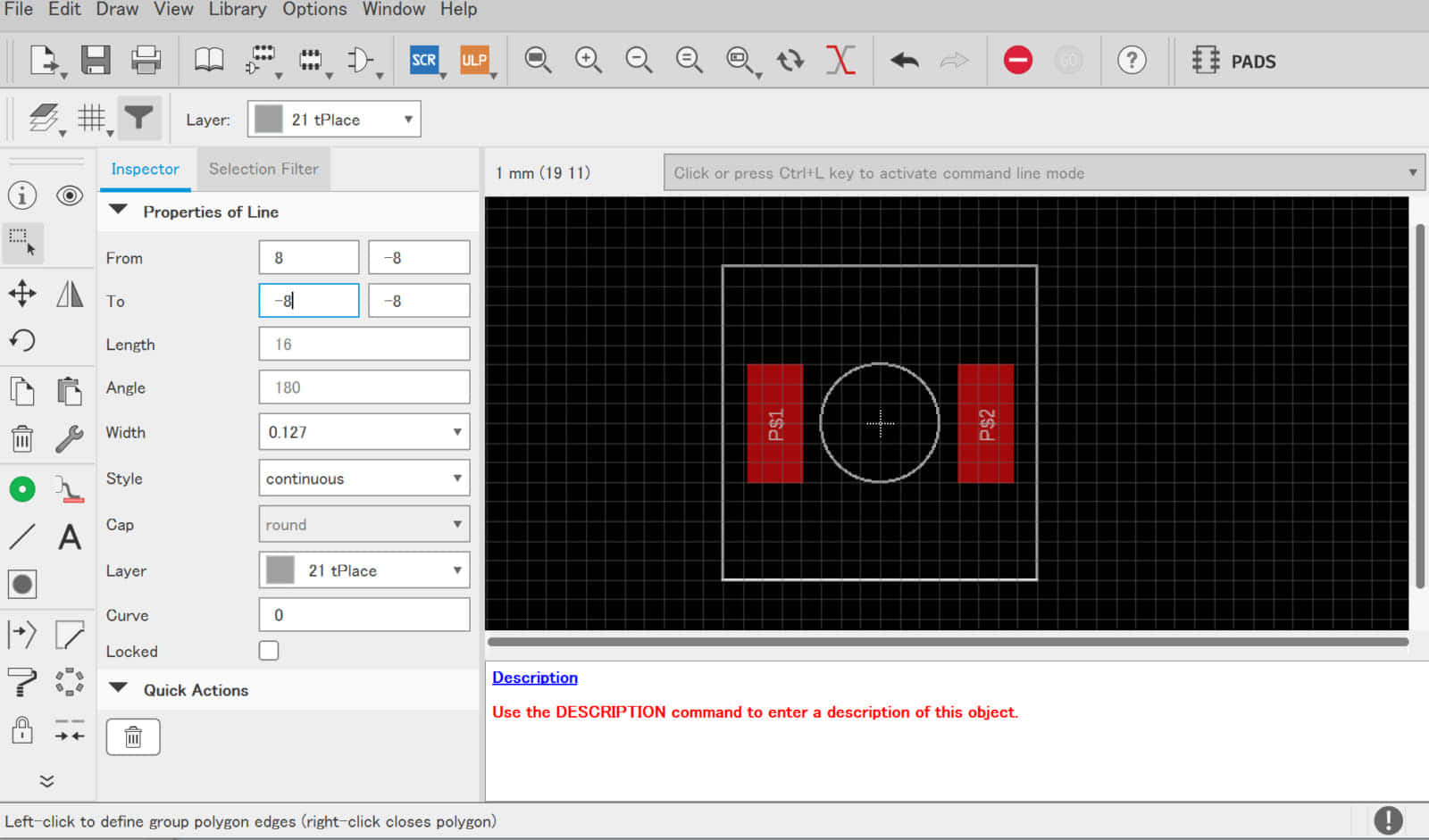
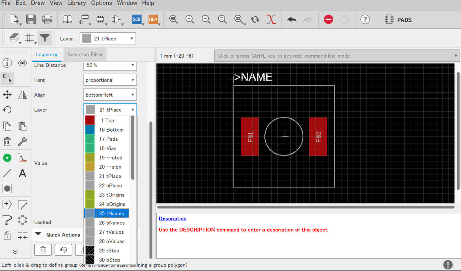
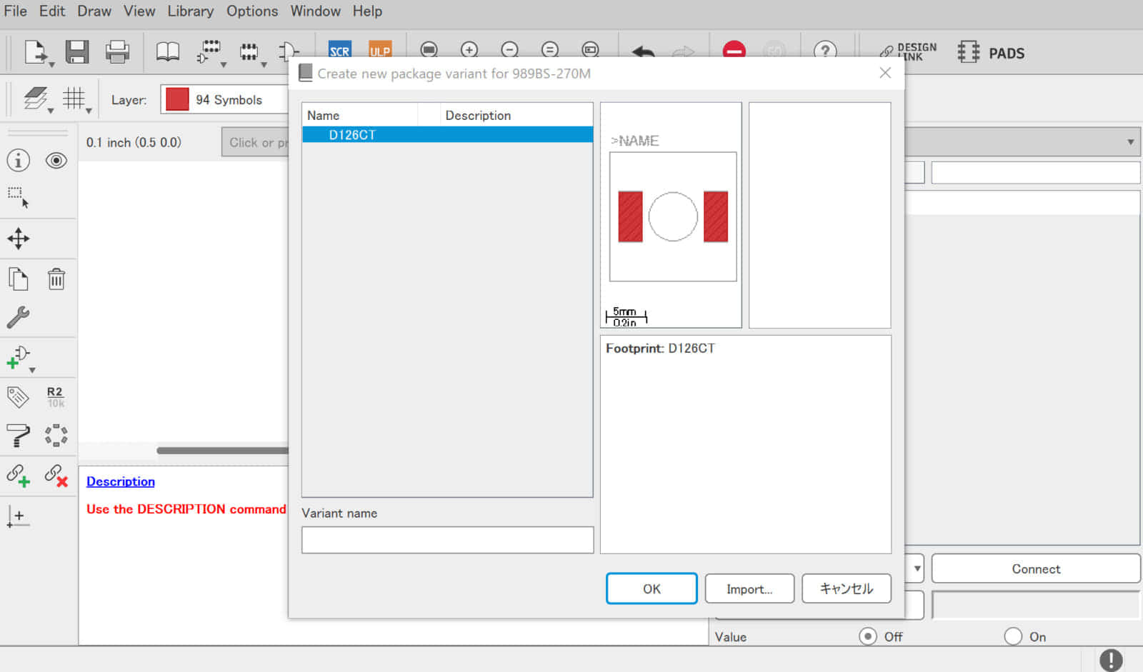
![](https://voltechno.com/blog/wp-content/uploads/2020/01/eagle-library017-768x481.jpg)
![](https://voltechno.com/blog/wp-content/uploads/2020/01/eagle-library007-768x481.jpg)
![](https://voltechno.com/blog/wp-content/uploads/2020/01/eagle-library008-768x481.jpg)
![](https://voltechno.com/blog/wp-content/uploads/2020/01/eagle-library009-768x481.jpg)
![](https://voltechno.com/blog/wp-content/uploads/2020/01/eagle-library010-768x481.jpg)
![](https://voltechno.com/blog/wp-content/uploads/2020/01/eagle-library011-768x481.jpg)
![](https://voltechno.com/blog/wp-content/uploads/2020/01/eagle-library012-768x481.jpg)
![](https://voltechno.com/blog/wp-content/uploads/2020/01/eagle-library013-768x481.jpg)
![](https://voltechno.com/blog/wp-content/uploads/2020/01/eagle-library014-768x481.jpg)
![](https://voltechno.com/blog/wp-content/uploads/2020/01/eagle-library015-768x481.jpg)
![](https://voltechno.com/blog/wp-content/uploads/2020/01/eagle-library016-768x479.jpg)
④ 「フットプリント」を作成
次に作成するのはフットプリントです。フットプリントとはパターン設計で用いられるプリント基板上の部品の配置と、部品と基板の接点を示すモデル図です。
フットプリントの作成では、電子部品のデータシートを参照して作成するのが一般的です。データシートには「推奨パターン図」が記載されているので、それを参考にパターンを作成します。
![](https://voltechno.com/blog/wp-content/uploads/2020/01/eagle-library018-768x479.jpg)
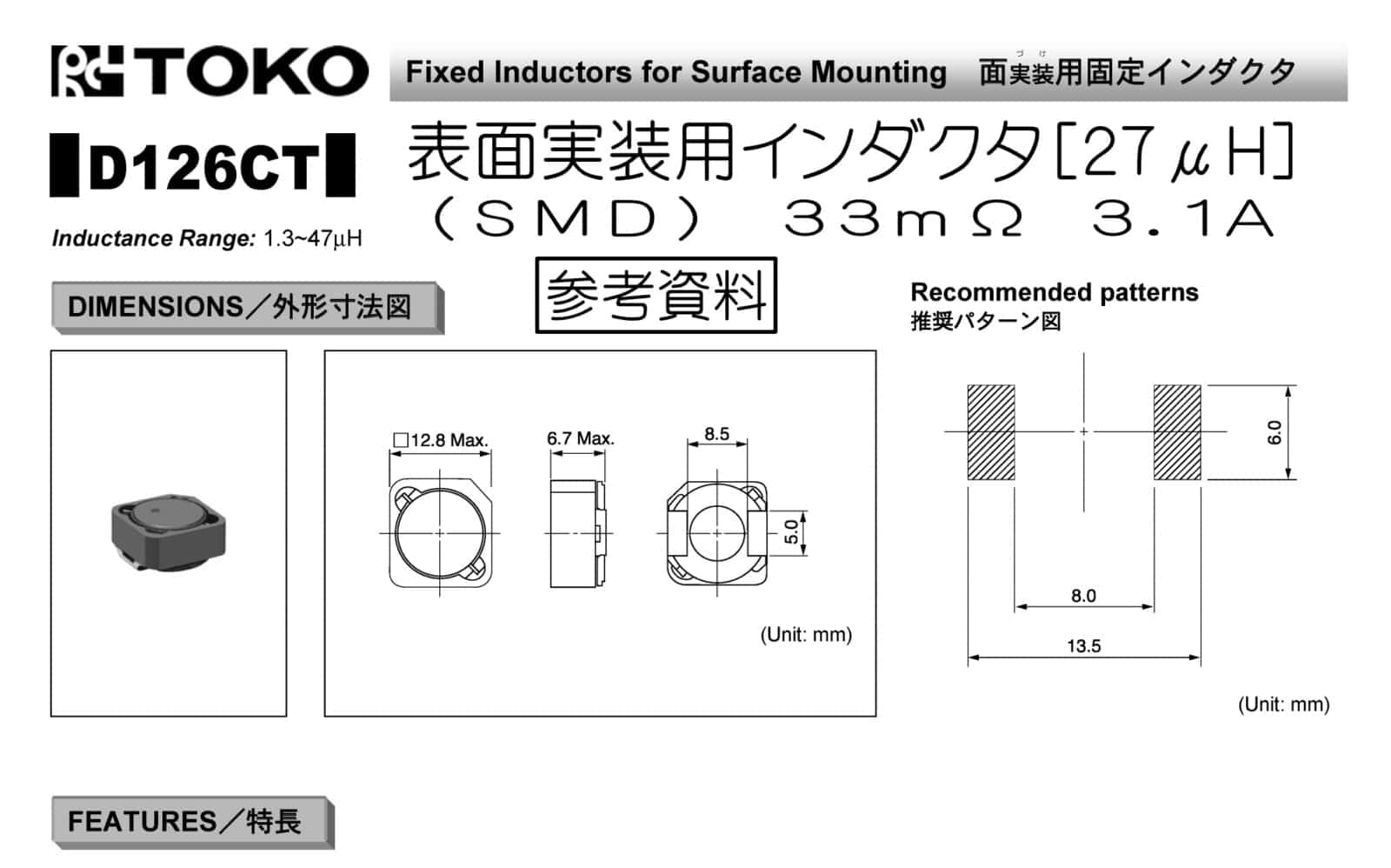
もし、データシートが無いまたはデータシートに推奨パターンの記載がない場合は実部品を測定してパターンを作成します。
![](https://voltechno.com/blog/wp-content/uploads/2020/01/topy-tacoil031-768x452.jpg)
![](https://voltechno.com/blog/wp-content/uploads/2020/01/topy-tacoil019-768x452.jpg)
![](https://voltechno.com/blog/wp-content/uploads/2020/01/topy-tacoil020-768x452.jpg)
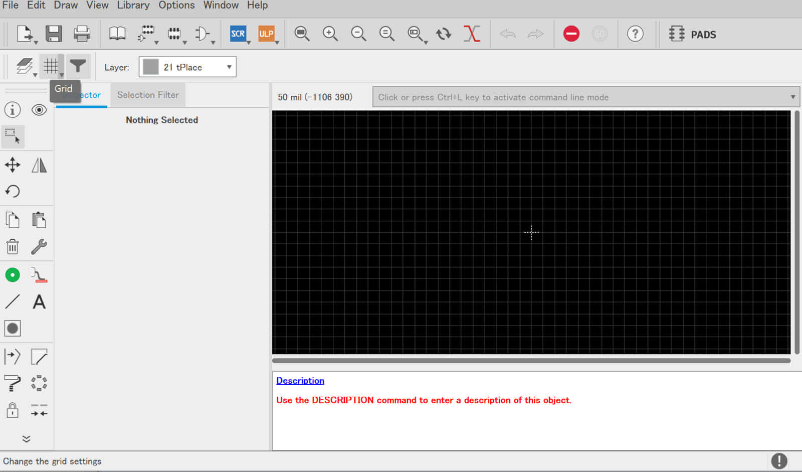
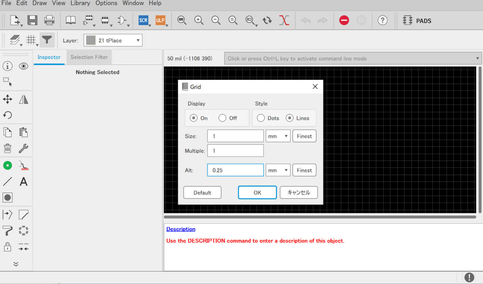
は0.25mmに変更する。AltはAltキーを押した時のみ有効になるグリッド寸法
![](https://voltechno.com/blog/wp-content/uploads/2020/01/topy-tacoil022-768x452.jpg)
![](https://voltechno.com/blog/wp-content/uploads/2020/01/topy-tacoil023-768x452.jpg)
![](https://voltechno.com/blog/wp-content/uploads/2020/01/topy-tacoil024-768x452.jpg)
![](https://voltechno.com/blog/wp-content/uploads/2020/01/topy-tacoil025-768x452.jpg)
![](https://voltechno.com/blog/wp-content/uploads/2020/01/topy-tacoil026-768x452.jpg)
![](https://voltechno.com/blog/wp-content/uploads/2020/01/topy-tacoil027-768x452.jpg)
![](https://voltechno.com/blog/wp-content/uploads/2020/01/topy-tacoil029-768x452.jpg)
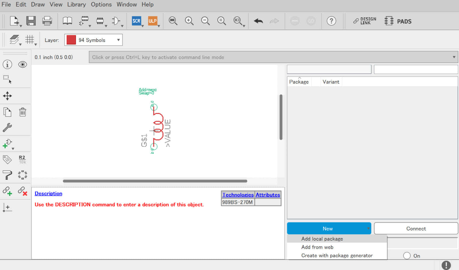
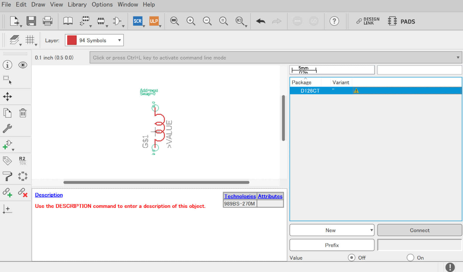
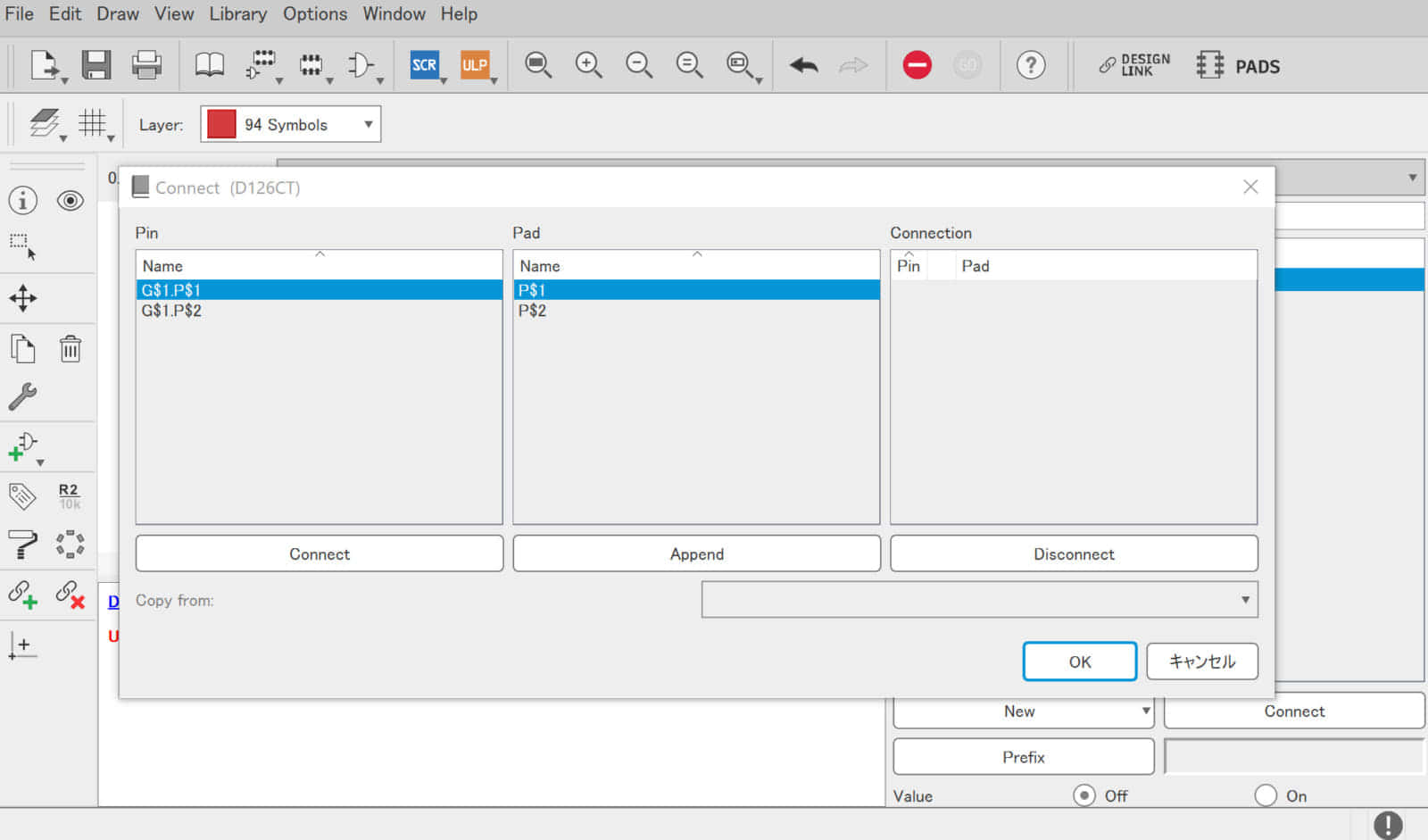
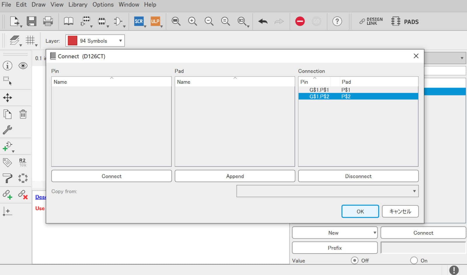
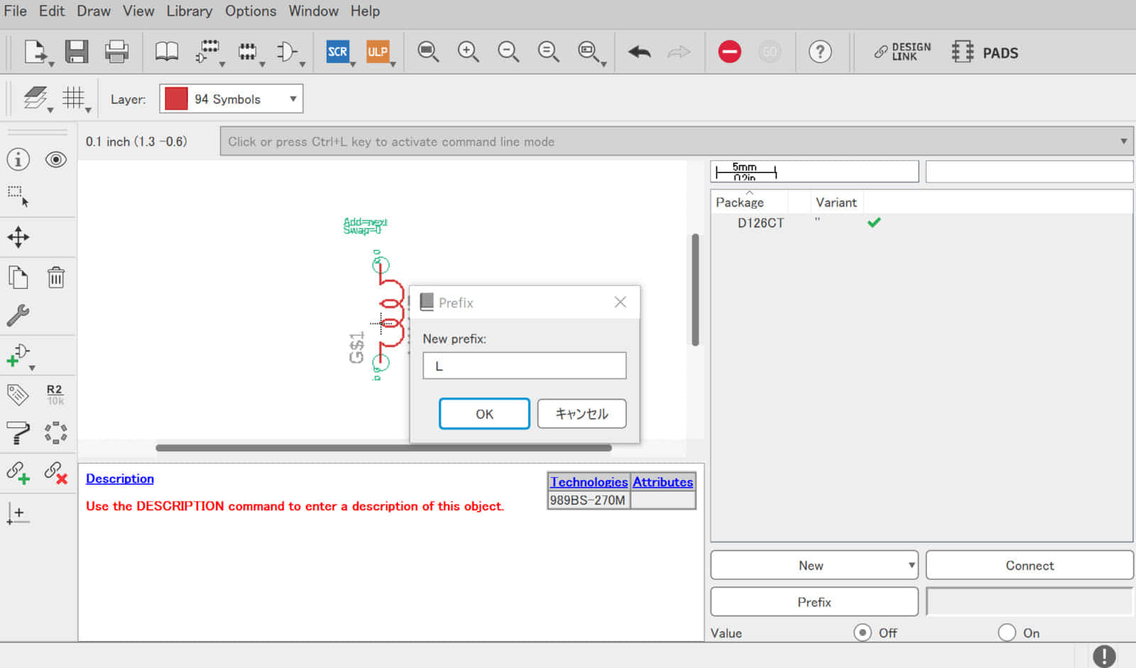
⑤ パーツ名とシンボル・フットプリントを関連付け
ここまで完成したら、最後はシンボルとフットプリントを関連付けして完成です。
この手順では、シンボルの端子とフットプリントの接点を紐づけて部品のコメントや接頭辞などを指定します。
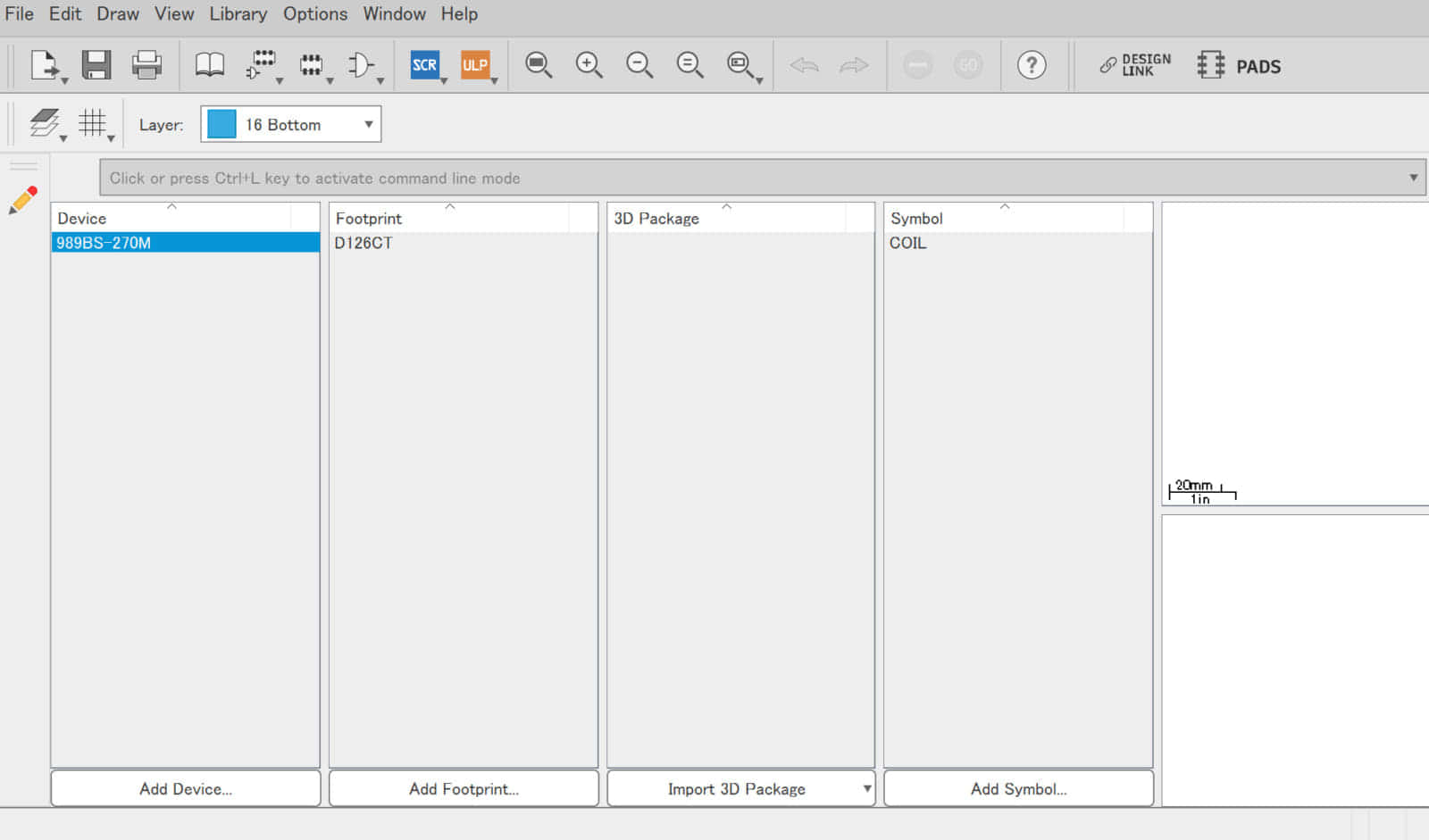
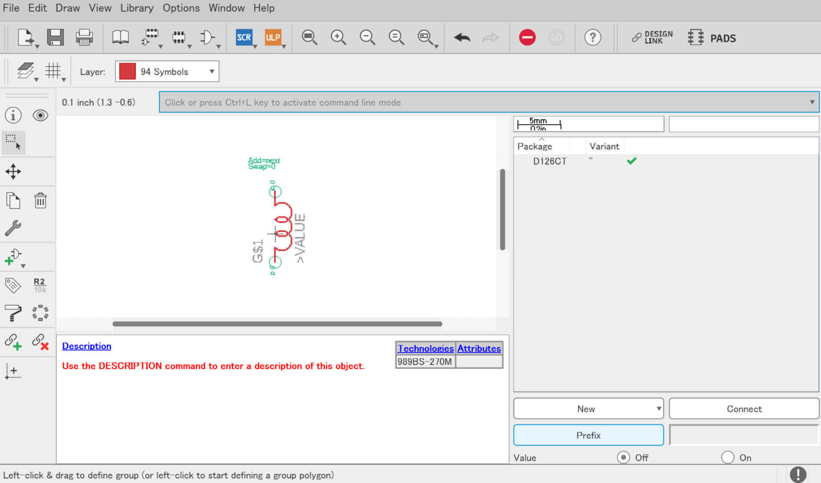
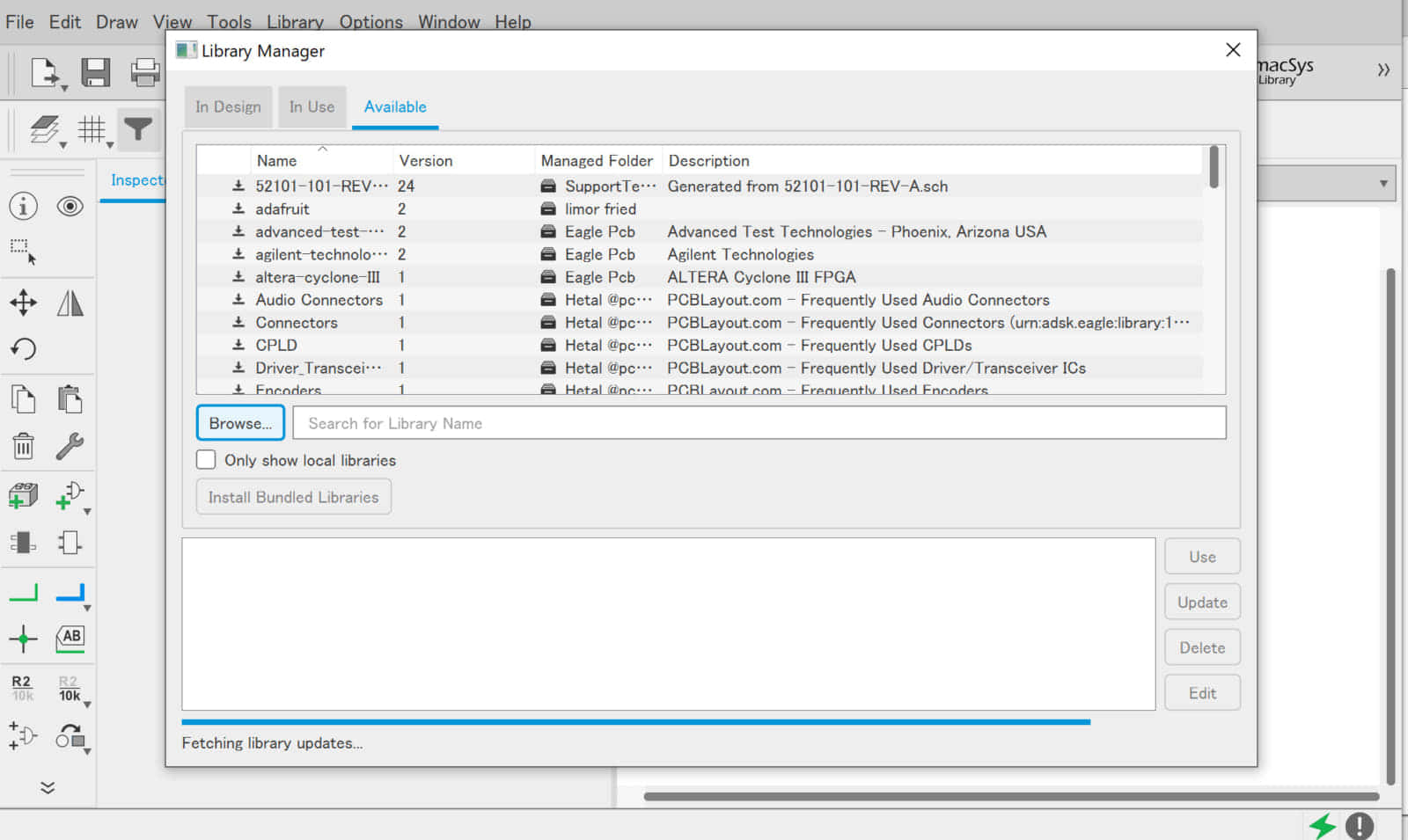
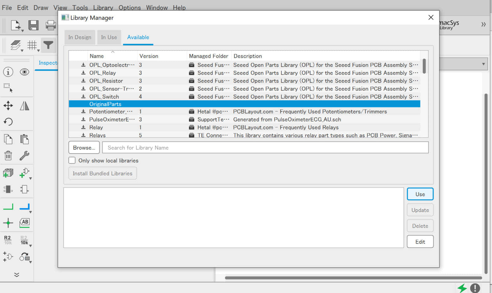
![](https://voltechno.com/blog/wp-content/uploads/2020/01/topy-tacoil032-768x452.jpg)
![](https://voltechno.com/blog/wp-content/uploads/2020/01/topy-tacoil034-768x452.jpg)
![](https://voltechno.com/blog/wp-content/uploads/2020/01/topy-tacoil035-768x452.jpg)
![](https://voltechno.com/blog/wp-content/uploads/2020/01/topy-tacoil037-768x452.jpg)
![](https://voltechno.com/blog/wp-content/uploads/2020/01/topy-tacoil038-768x452.jpg)
![](https://voltechno.com/blog/wp-content/uploads/2020/01/topy-tacoil039-768x452.jpg)
![](https://voltechno.com/blog/wp-content/uploads/2020/01/topy-tacoil040-768x452.jpg)
![](https://voltechno.com/blog/wp-content/uploads/2020/01/topy-tacoil043-768x452.jpg)
![](https://voltechno.com/blog/wp-content/uploads/2020/01/topy-tacoil045-768x452.jpg)
![](https://voltechno.com/blog/wp-content/uploads/2020/01/topy-tacoil046-768x452.jpg)
![](https://voltechno.com/blog/wp-content/uploads/2020/01/topy-tacoil047-768x458.jpg)
パーツライブラリを適用する
![](https://voltechno.com/blog/wp-content/uploads/2020/01/topy-tacoil048-768x458.jpg)
![](https://voltechno.com/blog/wp-content/uploads/2020/01/topy-tacoil049-768x458.jpg)
![](https://voltechno.com/blog/wp-content/uploads/2020/01/topy-tacoil051-768x458.jpg)
![](https://voltechno.com/blog/wp-content/uploads/2020/01/topy-tacoil052-768x458.jpg)
![](https://voltechno.com/blog/wp-content/uploads/2020/01/topy-tacoil054-768x458.jpg)
![](https://voltechno.com/blog/wp-content/uploads/2020/01/topy-tacoil055-768x458.jpg)
![](https://voltechno.com/blog/wp-content/uploads/2020/01/topy-tacoil056-768x458.jpg)